自制你的LoRa设备(英文:Building your LoRa devices)
Introduction
This page describes how to build LoRa end-devices. We mostly focus on Arduino platforms ( and describe how to connect and use various LoRa radio module: Libelium LoRa, HopeRF RFM92W/RFM95W, Modtronix inAir4/9/9B and NiceRF 1276.
Regarding the software, we use a modified, enhanced version of the SX1272 library initially developped by Libelium for their LoRa module based on the SX1272. The library now supports both SX1272 and SX1276, therefore it can be used with the Libelium LoRa, HopeRF RFM92W/RFM95W, Modtronix inAir4/9/9B and NiceRF LoRa1276. Actually most of SPI based LoRa modules should work fine with the library. Note that the original Libelium library to drive the LoRa module does not use DIO pins as many other libraries do, so there is no need to connect these pins. You can use other development codes using DIO pins by connecting the required pins that are mostly configured as follows DIO0 (RXdone or TX done), DIO1 (RX timeout) and DIO5 (ready). Of company, you have to check first. Some may also use the RST pin to reset the module.
The work presented here is part of the EU H2020 WAZIUP project (grant agreement number 687607, 2016-2019) which objective is to develop low-cost IoT solutions for deployment in sub-saharian African countries. Various applications are considered: water quality monitoring, cattle rustling, logistics and goods transportation.
Download: github (drop me a mail if you use our development so that we could advertise it)
- Arduino folder
- the modified SX1272 library (initial version comes from Libelium) with enhanced features: support of SX1276, LBT & CSMA-like, ...
- the code of a temperature sensor with an Arduino (tested on Uno, Mega, Due, Pro Mini, Nano, Micro, MO, Teensy32/31/LC, Ideetron Nexus), performing CS/LBT. Should work out-of-the box with the gateway
Radio modules
Libelium LoRa radio module
The Libelium LoRa module uses the Semtech SX1272 chip. Libelium has a multi-protocol shield adapted for the Libelium LoRa module. Visit this link for more information on the Libelium LoRa shield and module.
As the shield is not really necessary, you can reduce the cost of your device by connecting directly the radio module to your board: just connect the required SPI pins (MISO, MOSI, SCK and CS), VCC and GND to the corresponding pins on your board. Pin out diagrams for the Libelium LoRa module in XBee format is shown below (similar to the XBee WiFi). Pin 1 is VCC, pin 4 is MISO, pin 10 is GND, pin 11 is MOSI, pin 17 is CS and pin 18 is CLK.

Figure: XBee pin-out diagram for the Libelium LoRa module
We soldered the wires to the pin as shown in the figure below, using an intermediare 2mm 10-pin header.


Figure: using two 2mm 10-pin female socket to connect the LoRa module that has an XBee format. Right: the module is seen from the back side
HopeRF RFM92W/RFM95W
The HopeRF RFM92W (RFM95W) module is shown below. An adapter is needed to have the break-out pins (the RFM92W module is quite small) and most importantly the antenna plug (which is in Female SMA). The RFM92W (or RFM95W) with the adapter costs less than half of the Libelium LoRa which makes it quite attractive.
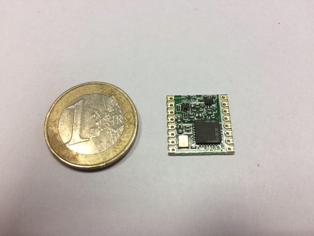


Figure: the RFM92W module (left), the RFM92W adapter (middle), the RFM92W and the adapter before soldering, comparison with the Libelium LoRa for size (right)


Figure: the RFM92W and the adapter, after soldering (left), ready to be plugged on the Raspberry (middle), the adapter pin-out (right)
After some delicate soldering, you will have the RFM92W/RFM95W module ready to be plugged on your board.


Figure: Arduino Nano (left) and Arduino Mega (right) connected to the RFM92W on the ICSP header
Using the Modtronix inAir9/9B (the inAir4 is also available for the 433MHz band)
This module has 2 advantages: it costs less than half of the Libelium LoRa (around 15€) and can come with the header pins already soldered! The left figure shows the radio module and the right figure shows the pin-out.


Figure: Modtronix inAir9 (left) and its pin-out diagram (right)
Our first tests show that the inAir is reliable. Given its low cost and readiness (the RFM92W/RFM95W needs some soldering) it is definitely a good choice. Note that there is an inAir9B with +20dBm transmit power but regulation is quite strict on such transmit power usage.
The NiceRF 1276
The NiceRF 1276 is a small form factor LoRa module. You can solder wires on the chip to get the standard SPI connections but it is delicate soldering task. Once done, just connect the required SPI wires like for the other LoRa modules.

Figure: NiceRF with its helicoidal antenna (an helicoidal antenne is usually not better, just smaller)
Dragino LoRa shield and Dragino GPS Hat with HopeRF RFM95W
Both the Dragino LoRa shield and Dragino LoRa GPS Hat are based on the HopeRF RFM95W. Therefore they are working like the latter described previously. The LoRa shield can be plugged directly into an Arduino board in the Uno format (with the ICSP) header and the LoRa GPS Hat into a Raspberry PI with the GPIO header.


Figure: Dragino LoRa shield (left) and Dragino LoRa GPS Hat (right)
However, it is possible to directly connect the usual SPI pins to any Arduino compatible board. For the LoRa shield, take the MISO, MOSI and CLK on the ICSP pin; CS is hard wired to pin 10. For the LoRa GPS Hat, the SPI pins are as followed (actually corresponding to the Raspberry GPIO header):

Figure (from Dragino wiki): Dragino LoRa GPS-Hat pin out.
We will see how in the next section how to connect these radio modules to your board.
Connecting the radio modules to the board
Arduino Uno, Mega or Due (Uno format)
For the Libelium LoRa, if you have the shield, you don't have to do anything: just connect the radio module in the left socket and you are ready to go to test the code of the provided temperature sensor.

Figure: an Arduino Mega with the multi-protocol radio shield
For all the radio modules, the simplest way is to use the board's ICSP header to connect the SPI pins: MISO, MOSI, SCK. In this way, it will work on Uno, Mega and Due. 3.3V is taken on the on-board 3.3V pin. GND pin can take any GND pin on the Arduino. On these "big" board, the CS pin should be connected to Digital 2 because it is the way the Libelium radio shield is wired (we wanted to preserve compatibility with this shield). For the Libelium LoRa you can use the module either with the shield, or without.

Figure: Arduino Mega pin out. Using the ICSP header will make it work on most of Arduino boards.
With the Dragino LoRa shield, if you plug the board into an Arduino board with Uno format, then, as indicated previously, CS is hard wired to use pin 10. However, our library defines CS to be pin 2 on the boards with Uno format. You actually have 2 solutions:
- in SX1272.h, change #define SX1272_SS 2 to #define SX1272_SS 10, or
- bend a bit pin 10 on the LoRa shield so that it will not be plugged into your board, and then take a M/M breadboard wire to link pin 2 to pin 10. In this way, the library is unchanged: The Uno, MEGA or Due is correctly detected and pin 2 will be used for CS. As pin 2 is now connected to pin 10 of the LoRa shield the radio module will correctly be selected.
With the Dragino LoRa GPS Hat, in addition to the MOSI, MISO and CLK that can be connected to the board's corresponding pins on the ICSP header, connect the LoRaNSS to pin 2. Here an example with a MEGA:

Figure: Connecting the Dragino LoRa GPS Hat to a MEGA. CS is on pin 2.
Arduino Pro Mini, Arduino Nano, Arduino Micro (small form boards)
On these small form factor board, it is not really possible to connect the radio shield so the only solution is to connect directly the radio module to the board's pins. The Arduino Pro Mini has not ICSP header while the Arduino Nano and the Micro does. If you want to use the ICSP header on the Nano and Micro you can do as described previously (pin 1 on the ICSP header of the Nano is the Reset pin). Figure below shows on the left the Arduino Pro Mini and on the right the Arduino Nano. If you don't use the ICSP, both platforms use pins 11 for MOSI, 12 for MISO and 13 for SCK. You have to use the ICSP header on the Micro because non of the SPI pins are wired to other digital pins.
On these small form boards, the library detects the Pro Mini, the Nano and the Micro boards to define pin 10 for CS instead of pin 2 on the Uno, MEGA and Due. So you have to connect the CS pin of the radio module to pin 10 of your board.


Figure: Arduino Mega (note that CS is on digital 2) with the inAir9 (left), Arduino Nano (note that CS is on digital 10) with the inAir9 (right)
While the Nano and Micro do have a 3.3V pin even if they run at 5V, the Pro Mini can be either in the 5V or 3.3V version. With the Pro Mini, it is better to really use the 3.3V version running at 8MHz as power consumption will also be reduced. Then power for the radio module can be obtained from the VCC pin which is powerd in 3.3v when USB power is used or when unregulated power is connected to the RAW pin. If you power your Pro Mini with the RAW pin you can use for instance 4 AA batteries to get 6V. If you use a rechargeable battery you can easily find 3.7V Li-Ion packs. In this case, you can inject directly into the VCC pin but make sure that you've unsoldered the power isolation jumper to avoid injecting current into the voltage regulator's output, see Pro Mini schematic on the Arduino web page. Be carefull with some low-cost Pro Mini clones that may not have this power isolation jumper. In this case, it is better to inject unregulated power into the RAW pin


Figure: Arduino Pro Mini (left), Arduino Nano (right)

Figure: Arduino Nano with the wires ready to be connected to a radio module: 10, 11, 12, 13, 3V3, GND


Figure: our LoRa temperature sensor based on an Arduino Pro Mini and the RFM95W radio module.
Connecting the Dragino LoRa shield to these small Arduino boards can simply be done by connecting pin 10 of the Dragino LoRa shield to pin 10 of your board to have the CS pin. Remind that the other SPI pins are taken from the LoRa shield ISCP header. To connect the LoRa GPS Hat, simply connect the MOSI, MISO and CLK as usual then LoRaNSS to pin 10.
Teensy 3.1 / 3.2 / LC
The Teensy platforms are also nice platforms to use and are fully compatible with the Arduino code with Teensyduino add-on. They are in a small format (about the size of the Nano or Pro Mini) and are quite powerful. Connecting the various LoRa module can be done as with the Pro Mini or Nano boards:pins 10 for CS, 11 for MOSI, 12 for MISO and 13 for SCK. Power for the radio module can be taken simply from the 3.3v pin (which can draw up to 250mA on the Teensy32 which is largely enough for the radio module even at 20dBm, on the Teensy 31 and LC the maximum is 100mA and should also be sufficient). You can get the pin out of the Teensy32/31 on https://www.pjrc.com/teensy/teensy31.html.

Figure: the Teensy 3.2 board

Figure: the Teensy 3.2 with an inAir9B radio module
Connecting the Dragino LoRa shield to the TeensyLC/31/32 boards can simply be done by connecting pin 10 of the Dragino LoRa shield to pin 10 of your board to have the CS pin. Remind that the other SPI pins are taken from the LoRa shield ISCP header. To connect the LoRa GPS Hat, simply connect the MOSI, MISO and CLK as usual then LoRaNSS to pin 10.
Using an Ideetron Nexus with an embedded RFM92W/RFM95W module
This is a special section for the Ideetron Nexus that is built around an Atmel328P and an RFM92W/RFM95W that is directly integrated into the board. It is equivalent to an Arduino Nano or Pro Mini with the RFM95W radio. Originally, the Nexus is driven by the previously mentioned light LoRaWAN library from Ideetron but it can actually be used with our modified SX1272 library. If you want to program the Nexus, use in the Arduino IDE the Mini as the target platform. You will need a regular FTDI breakout board as explained in this Arduino tutorial (for the Pro Mini but the connections are the same) but make sure that you get the 3.3v version of the breakout. Again, the library can detect the Mini platform and sets the CS pin to digital 10 which is the pin used by the Nexus. The circuit diagram of the Nexus can be found here. Just connect the antenna and it should work. If you want to power the Nexus, you can inject a maximum of 18v on the PWR-RAW pin that is connected to a voltage regulator delivering the 3.3v to the board.


Using an Adafruit Feather 32u4 with an embedded RFM95W module
This is a special section for the Feather 32u4 from Adafruit. The Feather 32u4's heart is an ATmega32u4 clocked at 8 MHz and running at 3.3v level. Details on this board can be obtained from here.

Figure: the Adafruit Feather 32u4
The embedded RFM95W is already connected therefore MISO, MOSI, CS and CLK connections are already there. They can be programmed with the Arduino IDE by following instructions from here. Our library works fine with this board: the SX1272.h has been updated to set CS pin to pin 8 and RST pin to pin 4 which is the way the RFM module is wired to the ATmega32u4.
Although it is not been tested with the Feather M0 with the RFM95W, the library should work as the wiring is the same as the Feather 32u4.
Using an ESP8266 with an RFM95W module
I want to reference this nice port to ESP8266 with an RFM95W module by Marcio Miguel: https://github.com/marciolm/EspComLoRa

Figure: ESP8266 from Marcio Miguel
Connecting to a board that is not described here
If your board has SPI pins then it is most likely that it will work. Just connect the SPI pins of the radio module and those of your board together. For the CS pin, the SX1272.h file defines the following pin according to the board model:
#if defined ARDUINO_AVR_PRO || defined ARDUINO_AVR_NANO || defined ARDUINO_AVR_MICRO || defined ARDUINO_AVR_MINI \
|| defined __MK20DX256__ || defined __MKL26Z64__
#define SX1272_SS 10
#elif defined ARDUINO_AVR_FEATHER32U4 || defined ARDUINO_SAMD_FEATHER_M0
// on the Adafruit Feather, the RFM95W is embeded and CS pin is normally on pin 8
#define SX1272_SS 8
#undef SX1272_RST
#define SX1272_RST 4
#else
#define SX1272_SS 2
#endif
As the you see, the library detects the Pro Mini, the Nano, the Micro, the Mini (for Ideetron Nexus) and the Teensy31/32/LC boards to define pin 10 for CS instead of pin 2 for the other boards (e.g. the Uno, MEGA, Due,...). For special case of Feather 32u4 and Feather M0 the CS pin will be pin 8 as you cannot change the wiring. If you are not sure, use pin 2 and see whether the transceiver is detected or not.
Important notice on powering the LoRa radio module
SX1272 or SX1276 are working with 3.3v. The radio modules are connected either with a 3.3v output pin (or 5v with a regulator if you want), when available on the board, or with a digital pin set to high level (in this case be sure that your board is in 3.3v version). Be aware that the maximum current that these pins can support is usually 40mA. From the Semtech SX127x documentation, the transmit current is about 20mA and 29mA with RFO at +7dBm and +13dBm respectively (with our library it is mode 'H' and 'M' respectively); and about 87mA with the PA_BOOST at +17dBm. In our library, power mode 'x' use the PA_BOOST but with a limit to +14dBm for using the RFM92W/95W and the inAir9B that need the PA_BOOST. However, we have observed that for the RFM95W and inAir9B radio modules, setting power to 'x' on the Pro Mini or Nano is not working (no error is reported but transmission failed). They work fine on the Uno, Mega and Due. If you use RFM92W or inAir9, then the power mode 'x' works on all boards.
If you want to overcome these max current limitations, you can get power from either the USB connector with a 5v to 3.3v regulator; or if you use a battery, get a 3.3V from the battery directly (again with a reulator if needed). Usually the max current is about 100mA. More info can be found on the Arduino pin current limitation page.
Some words about LoRaWAN end-devices
Our modified SX1272 library is not LoRaWAN compatible. It is not it's purpose. You can build LoRaWAN end-devices by either using one of the LoRaWAN implementations that exists (LMIC and LoRaMAC-Node) with a LoRa module plugged in a board. Thomas Telkamp has a great port of LMIC for Arduino. Or you can use a radio module that already has an implementation of LoRaWAN. In most cases, you will be able to issue commands to the radio module for realizing LoRaWAN operations. Check this page from TheThingNetwork for a nice summary of LoRa/LoRaWAN hardware: http://thethingsnetwork.org/wiki/Hardware/OverviewNodes.
I also want to mention a very light implementation of LoRaWAN that was originally intented for the Ideetron Nexus board (ATmega328P and RFM95W) but that compile straight away on most of Arduino boards with the RFM95W module connected accordingly (it uses DIO0 for RxDone, DIO1 for Timeout and DIO5 for Ready). It is worth looking at it if you want to start understanding a bit the basic of LoRaWAN: https://github.com/Ideetron/RFM95W_Nexus by Gerben den Hartog. The AES implementation is quite lightweight and I've tested the code on both an Arduino MEGA2560 and an Arduino Pro Mini. Of company, only a minimum support of LoRaWAN is provided but it is a nice starting point. Matthijs Kooijman merged the LMIC port of Thomas Telkamp with the lightweight AES library of Gerben den Hartog to propose and LMIC lightweight LMIC port. Maarten Westenberg also contributed in some way for a more lighweight LoRaWAN stack with support of the ESP8266. Of company, only a minimum support of LoRaWAN is provided but it is a nice starting point.
Note that the RFM92W/RFM95W adapter does not have the DIO5 pin. The pin out of the RFM92W/95W module is illustrated in the left figure. The right figure shows how we've just soldered a wire to get DIO5.


Figure: RFM92W/95W pin-out (left), DIO5 connected (right)
Enjoy!
C. Pham
Author: C. Pham, LIUPPA laboratory, University of Pau, France. http://web.univ-pau.fr/~cpham
last update: Apr 2nd, 2017.
Follow this link for building your own LoRa gateway
Get the step-by-step tutorial on how to build your low-cost, low-power LoRa device with an Arduino Pro Mini
您的留言或需求: